2015-3-9 01:39:21 Author: grymoire.wordpress.com(查看原文) 阅读量:1 收藏
I purchased a HackRF device from Kickstarter, and some people recommend that shielding will help improve the reception. Nooelec sells an optional shield, but I thought a metal case would provide better shielding, for a few more dollars. Mike Ossmann says the HackRF is made to work with the Hammond 1455J1201 so I searched Element14’s site and bought a black case. At the time the case was $20.68, but as I write this it seems to have jumped up to $35. Mouser sells this case for $18.70.
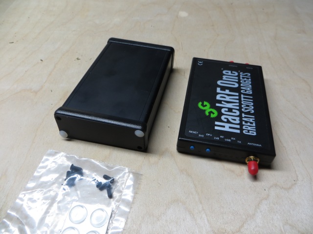
Here is the Hammond case shown next to the original plastic case
And here is the case taken apart
I wanted to drill the holes carefully, and make it look nice. I asked on the hackrf mailing list for some information on the location of the holes, and Stefano Probst game me a link to the output from Kicad, which he’s made available here.
However, I wasn’t going to use any sort of CNC-controlled mill/drill. I was going to drill the holes by hand. How was I going to accurately drill the holes from the above file?
First I examined the specifications of the Hammond case. This says the end plates are 3.071 inches long. So I just needed a way to print out the SVG file to be the save size. I used the free software Sure Cuts-a-lot 4 software, which had a ruler tool in the program that allowed me to measure the size of the end plate before I printed it. Then I cut out the paper.
I checked that the paper was the same size as the end plate. I then used rubber cement to glue the paper onto the end plate, carefully lining up the edges.
Then I used a punch to mark the exact center of the holes.
To be more precise, I first used a scriber or prick punch to mark the center of the hole. Then I examined the mark carefully to make sure it was in the exact center (this is important). Then I used an automatic center punch (or you can use a simple metal punch and a hammer) to make the hole deeper.
If you didn’t get the holes in the proper place, you can place the punch in the correct position, which may be a little on the other side of the center, and try again. By overshooting the center a little, the new hole will “fill in” towards the old hole, and end up between the new and old positions.
Once the holes are correctly marked, and made deep enough for a drill bit to go through the metal without wandering, you should fasten the end plate to a wooden block. I used 6×3/4″ wood screws to do this:
Make sure you have the plates on the correct side, as the screw holes are countersunk, and you want that side to be upward.
This wooden block is a safety precaution, because drilling metal plates can be dangerous when the drill jams in the metal and the entire plate starts revolving around the drill bit. The wooden block also provides a backing board for the through holes.
Now we have to drill the holes. I used a drill gauge to measure the hole diameters. The drill bits you need are 5/64″, 5/32″ and 1/4″. You should use the 5/64″ to drill pilot holes for the larger holes. I used a table-top drill press, but a hand drill should also work.
The odd-shape USB connecter cut-out is made from smaller holes used as a pilot, and then a small flat needle file is used to smooth out the cut-out:
The holes may have a rough edge, so you probably want to remove these edges. You can use sandpaper, or a deburring tool. To use a deburring tool, insert the blade and spin it around the hole. You can also use a counter-sink bit. The little holes for the LED’s were too small to allow this. I used a file to eliminate the burrs in that case.
I then testing the fit by hand:
I did have to use a round needle file to make one of the holes a little wider. But everything fit together very nicely.
I plan to add a shielding strap to the case, and test the changes in RF sensitivity to the plastic case vs the aluminum case.
I did have a little problem with the screws into the case. I may have to re-tap the threads in the holes.
如有侵权请联系:admin#unsafe.sh


