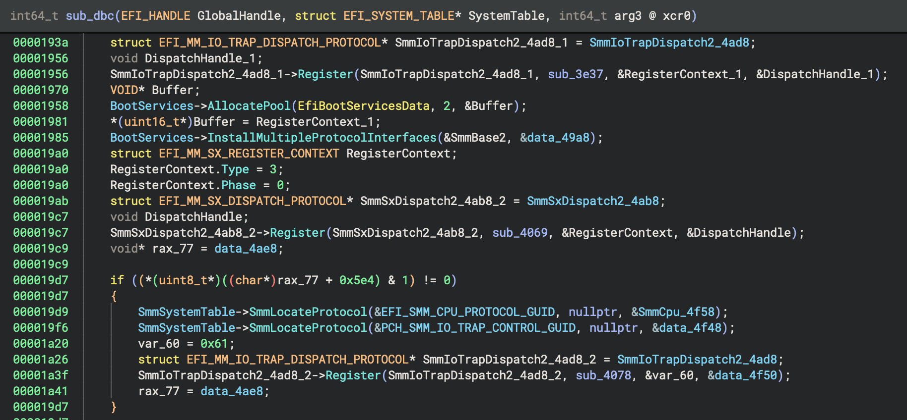
The Unified Extensible Firmware Interface (UEFI) is a specification that defines the architecture of firmware used for booting computers. It contains the initial code that runs on most modern PCs and mobile devices, operating at the highest privilege levels before the operating system loads. This makes UEFI a fascinating area for reverse engineering.
Let’s delve into some firmware samples and demonstrate how Binary Ninja and our official EFI Resolver plugin can automate the analysis of UEFI binaries. The features highlighted in this blog post represent a culmination of efforts that began prior to the release of Binary Ninja 3.5. This ongoing work includes recent contributions by Zichuan, one of our summer interns!
Brief Overview of UEFI
UEFI was designed to replace the Basic Input/Output System (BIOS) and is now widely adopted by leading vendors such as Intel, Apple, and Google for booting operating systems like Windows, Linux, and macOS. This section offers a brief overview of UEFI design; however, for a complete understanding, we recommend you review the full 2205-page UEFI specification before you proceed. Don’t worry, this blog will still be here in a few weeks when you’re finished.
UEFI Phases
UEFI firmware consists of (7) primary phases:
-
Security Phase (SEC) - This phase is regarded as the software root-of-trust (RoT) on systems that boot UEFI. However, many systems use hardware-based RoT mechanisms, such as Intel BootGuard, to verify SEC and PEI. SEC execution often starts at the reset vector, directly from Flash. It sets up initial memory and is also responsible for the initial handling of sleep states. SEC can also verify PEI, prior to handing off execution.
-
Pre-EFI Initialization (PEI) - This phase is responsible for initializing the system hardware (chipset, RAM, etc.). Like SEC, PEI code often runs directly from Flash in a resource-constrained environment. During PEI, PEI modules (PEIM) are discovered and dispatched by the PEI Foundation. PEI modules interact with the system hardware, install PEIM-to-PEIM interfaces (PPI) to share functionality, and prepare the system for the DXE phase.
-
Driver Execution Environment (DXE) - This phase is where the majority of the system initialization is performed. The DXE Dispatcher is responsible for finding and loading DXE modules in the correct order. The DXE drivers provide services for console and boot devices. DXE works together with Boot Device Selection (BDS) to boot the operating system.
-
Boot Device Selection (BDS) - This phase is responsible for identifying and selecting the boot device and enforcing the platform boot policy.
-
Transient System Load (TSL) - This phase is often where the boot loader runs and terminates UEFI boot services. However, some systems skip this phase and the operating system terminates boot services.
-
Runtime (RT) - This phase is where UEFI hands off execution to the operating system. The UEFI runtime services remain available to support the operating system. Runtime services trap System Management Interrupts (SMI) as the operating system attempts to interact with OEM hardware in System Management Mode (SMM).
-
After Life (AL) - Nobody knows what happens in the after life…
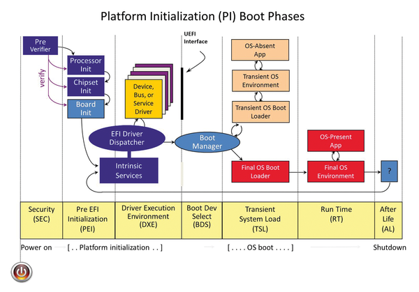
(Image from Tianocore documentation)
Firmware File System (FFS)
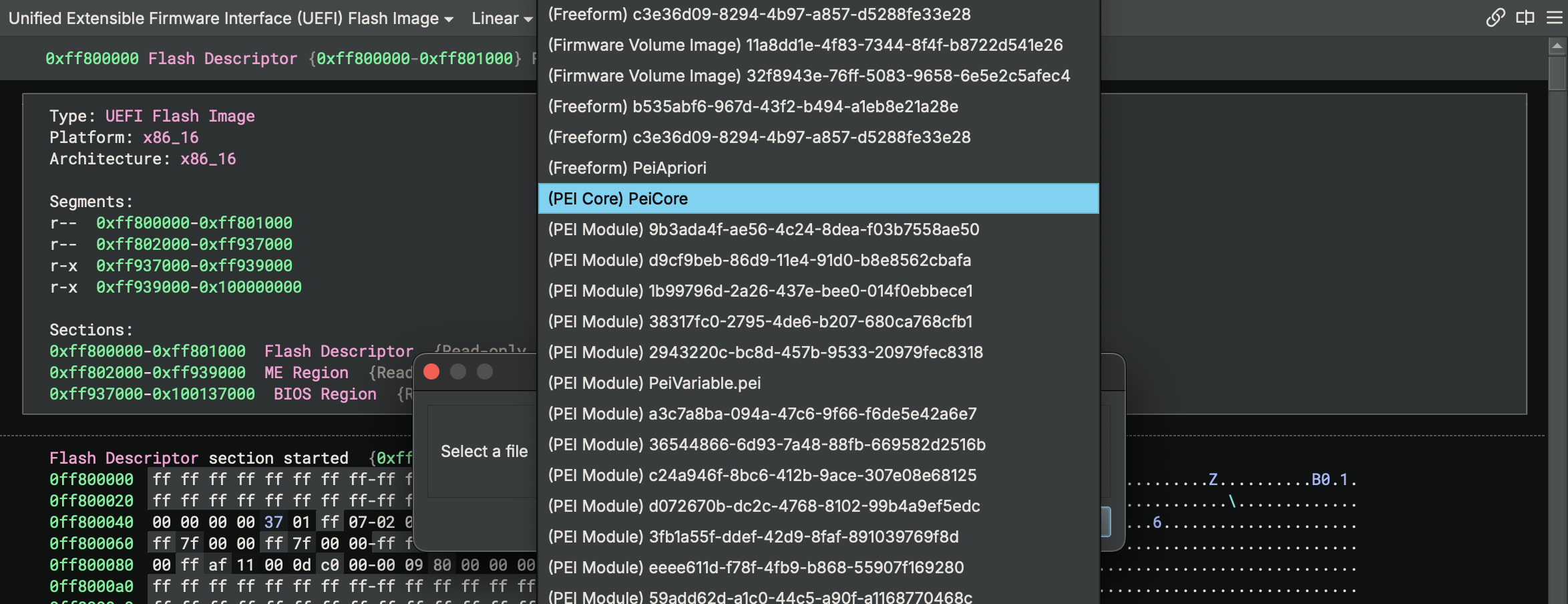
UEFI binaries are bundled in a container format known as the Firmware File System (FFS). FFS consists of many components and layers including volumes, files and sections. Within FFS file sections reside the interesting binaries such as Pre-EFI Initialization (PEI) modules and Driver Execution Environment (DXE) modules. There are many tools that can be used to parse FFS files and extract UEFI binaries. The most commonly used tool is UEFITool though of course we’re partial to EFI Inspector, an unofficial Binary Ninja plugin.
UEFI Binary File Formats
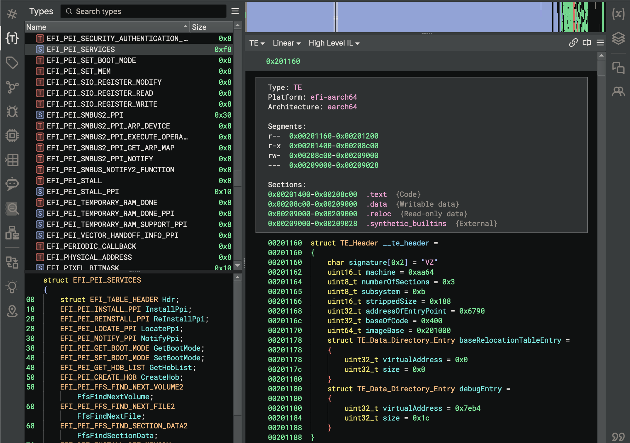
UEFI PEI and DXE modules are most commonly in either Portable Executable (PE) or Terse Executable (TE) format. Binary Ninja has supported the PE file format since its inception. The TE format is designed to reduce the overhead of the PE/COFF headers in PE images. This allows for smaller file sizes for PEI modules that run early in boot and must reside in Flash (uncompressed). TE files are nothing more than modified PE files. The toolchains that create TE files first emit a PE. Then they strip the PE/COFF headers and replace them with a smaller TE header. With the release of Binary Ninja 4.1, we added a BinaryView for loading Terse Executables. Like all of our other BinaryViews, the TE View is open source!
UEFI Protocols
To modularize UEFI firmware, the UEFI specification introduces protocols and services. UEFI services provide system-wide
functionality for accessing NVRAM variables, locating and registering protocol interfaces and more. UEFI protocols are
interfaces that are registered for use by external modules and drivers. These interfaces include PEIM-to-PEIM interfaces
(PPI), DXE protocol interfaces, SMM protocol interfaces and more. UEFI protocols are registered with PEI and boot
services using a 16-byte globally unique identifier (GUID) by calling functions such as InstallProtocolInterface,
which is provided by EFI boot services and Management Mode (MM) System Table. PEI modules use InstallPpi, which is
provided by PEI services. Other functions can register multiple protocols, and other APIs query the pointer to protocol
interfaces (LocateProtocol, LocatePpi, etc.).
Binary Ninja EFI Platforms and Types
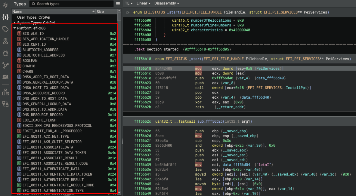
Native EFI platforms have been implemented in Binary Ninja for UEFI module analysis. Binary Ninja platforms have the ability to auto-recognize the platform from file format metadata, define supported calling conventions and populate the binary view with platform types on load of the binary. UEFI platforms for x86, x86-64, AArch64, ARMv7 and Thumb-2 were introduced in Binary Ninja 3.5. With the addition of new EFI platforms, Binary Ninja will automatically recognize UEFI modules on load.
Platform types have also been added to Binary Ninja for EFI platforms. The first set of EFI types was added to Binary Ninja 3.5 and included core EFI types as well as types associated with EFI runtime services, boot services and DXE protocols. Binary Ninja 4.1 introduced types for System Management Mode (SMM), PEI services and PEIM-to-PEIM Protocol Interfaces (PPI). These types can be explored in the Binary Ninja type browser after loading a binary for an EFI platform. Don’t forget to check out Binary Ninja’s type cross-references feature!
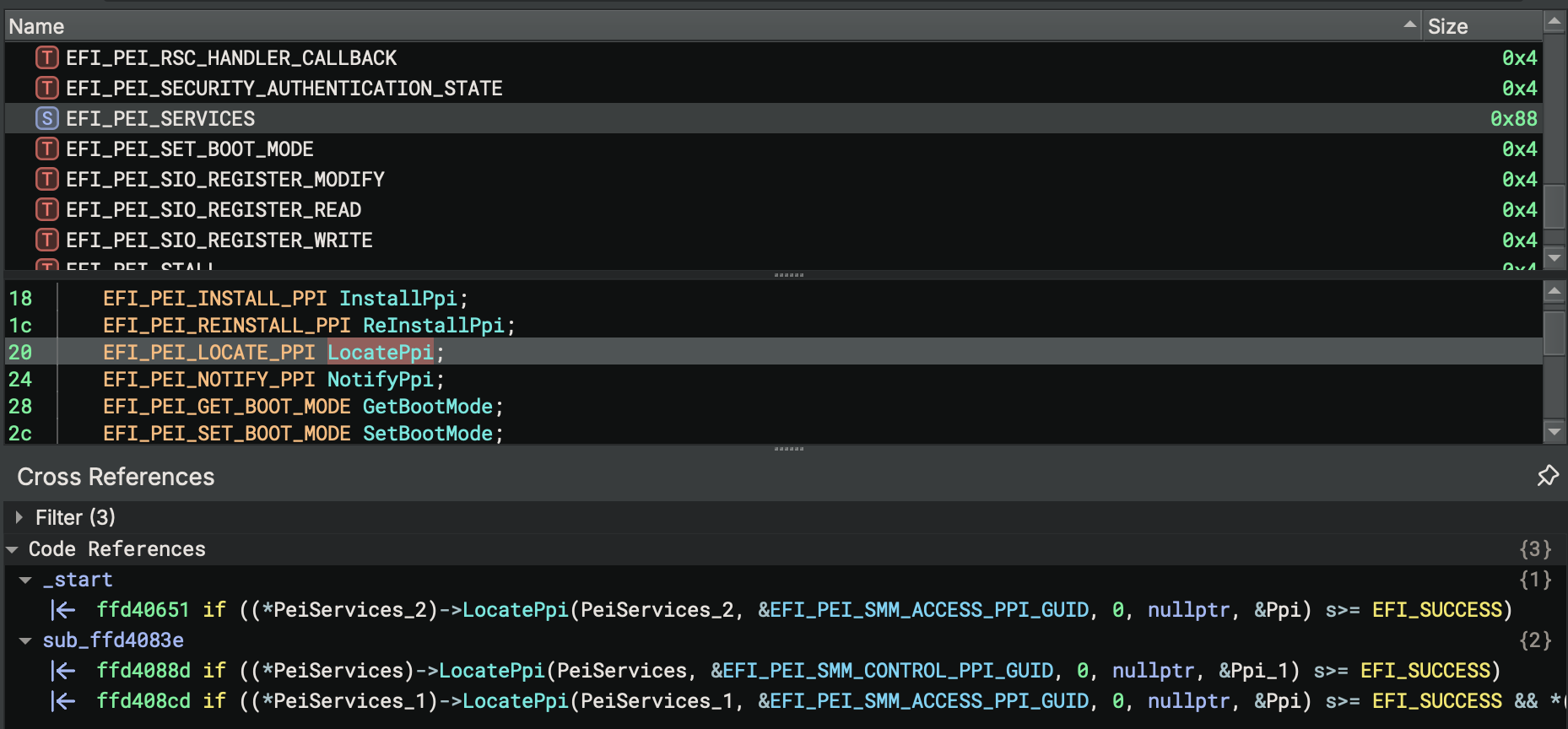
EFI Resolver
EFI Resolver is an official Binary Ninja plugin that automatically discovers EFI protocol interfaces and propagates type information for UEFI binaries. EFI Resolver 1.0.0 was initially released with support for DXE modules and with the ability to propagate types such as the EFI system table, runtime services and boot services. Since its initial release, support has been added for resolution of SMM protocol interfaces, PEI module type propagation and PPI discovery.
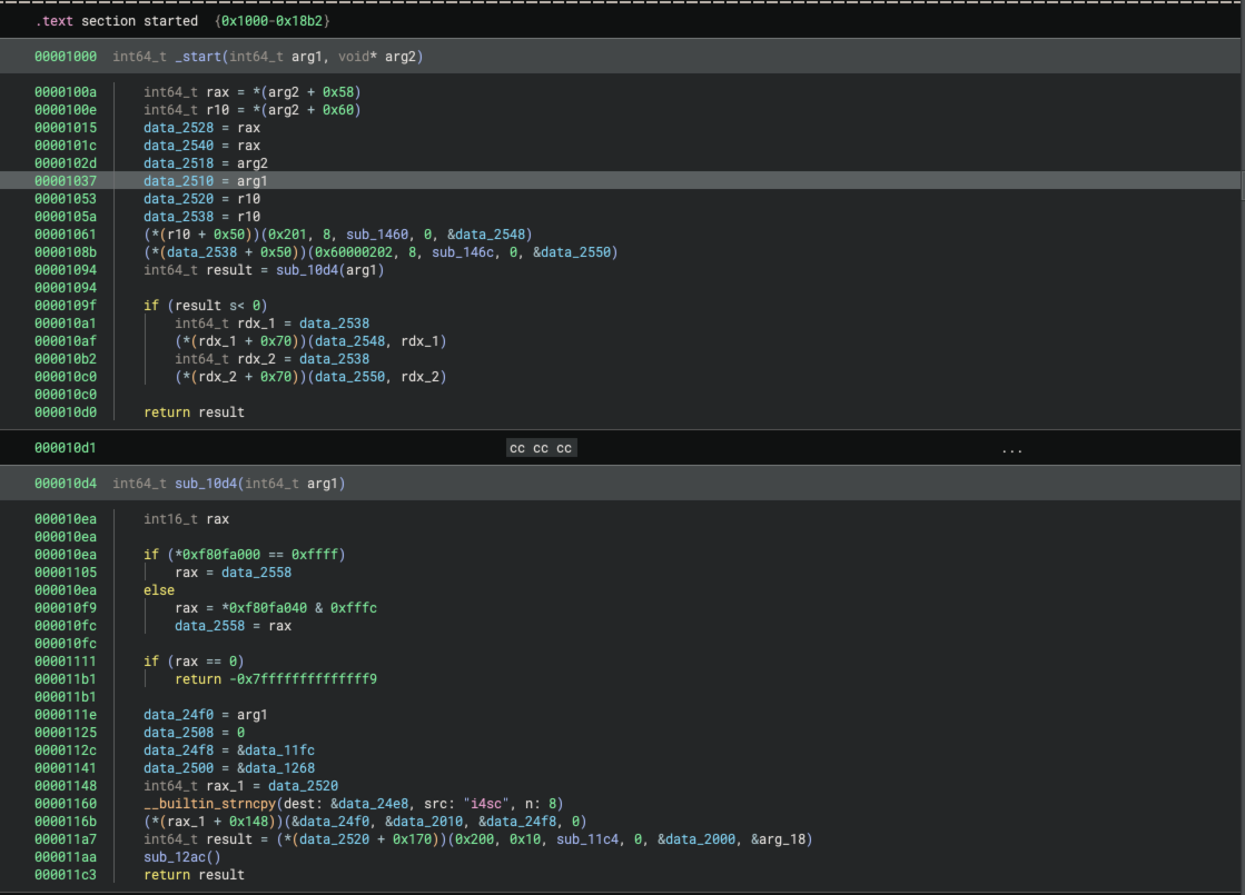
DXE Module Type Propagation
EFI Resolver type propagation analyzes Binary Ninja High Level IL (HLIL) starting at the EFI module entry point. The DXE module entry point function takes two parameters: the image handle and a pointer to the EFI system table. The type for the module entry point function is:
EFI_STATUS _ModuleEntry(EFI_HANDLE ImageHandle, EFI_SYSTEM_TABLE* SystemTable)
EFI Resolver’s first step is to propagate the EFI_SYSTEM_TABLE type from the SystemTable parameter to global and
local variable assignments within the entry point function and to callee functions where SystemTable is supplied as a
parameter. The EFI_SYSTEM_TABLE structure contains pointers to the EFI runtime services (EFI_RUNTIME_SERVICES) and
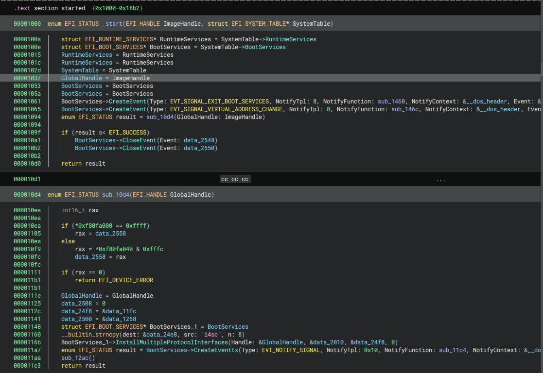
the EFI boot services (EFI_BOOT_SERVICES). The figure below shows a function that is called from the module entry
point. EFI Resolver successfully identified the system table as the second parameter, propagated the assignment of the
EFI runtime services pointer to a global data variable and renamed the global data variable to RuntimeServices. It
also propagated the EFI_BOOT_SERVICES type to a global variable that it renamed to BootServices.

As EFI Resolver analyzes the HLIL instructions, it identifies additional functions that make assignments from global data variables which contain pointers to boot services, runtime services and the system table. The plugin then propagates these types and name variables throughout the binary.
DXE and SMM Protocol Discovery
As previously mentioned, UEFI protocols are installed using the InstallProtocolInterface API which is exposed by the
EFI boot services. The EFI_BOOT_SERVICES structure includes function pointer members for InstallProtocolInterface,
LocateProtocol and OpenProtocol functions. InstallProtocolInterface is responsible for registering a protocol
interface by GUID. LocateProtocol is used to look up protocol interfaces (by GUID) and OpenProtocol is used to
register that the protocol interface is being consumed by the module. The types for these functions are:
EFI_STATUS (* EFI_INSTALL_PROTOCOL_INTERFACE)(EFI_HANDLE* Handle,
                                             struct EFI_GUID* Protocol,
                                             EFI_INTERFACE_TYPE InterfaceType,
                                             VOID* Interface)

EFI_STATUS (* EFI_LOCATE_PROTOCOL)(struct EFI_GUID* Protocol,
                                   VOID* Registration,
                                   VOID** Interface);

EFI_STATUS (*EFI_OPEN_PROTOCOL)(EFI_HANDLE Handle,
                                EFI_GUID* Protocol,
                                VOID** Interface,
                                EFI_HANDLE AgentHandle,
                                EFI_HANDLE ControllerHandle,
                                EFI_OPEN_PROTOCOL_ATTRIBUTES Attributes);

EFI_STATUS (*EFI_HANDLE_PROTOCOL)(EFI_HANDLE Handle,
                                  EFI_GUID* Protocol,
                                  VOID** Interface);
Once EFI Resolver propagates the pointer for boot services throughout the binary, it locates all variables typed as
EFI_BOOT_SERVICES and identifies indirect function calls through BootServices->HandleProtocol,
BootServices->OpenProtocol and BootServices->LocateProtocol function pointers. EFI Resolver queries the parameter
register values and resolves the address of the protocol GUID and the variable that will be used to store the pointer to
the protocol interface. The figure below shows the HLIL instruction graph for a call to BootServices->LocateProtocol.
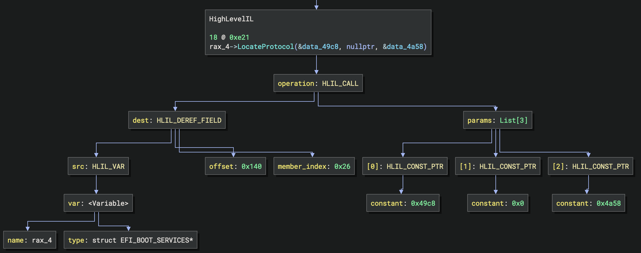
The first parameter (data_49c8) contains the pointer to the protocol interface GUID. The third parameter
(&data_4a58) is a pointer to the variable that will store the pointer to the interface. EFI Resolver reads the 16-byte
GUID at data_49c8 and compares it to its list of GUIDs for known protocols. If it discovers the GUID and protocol, it
renames the data_49c8 global variable. It also renames the data_4a58 global variable containing the interface
pointer and assigns the protocol interface structure type. data_49c8 becomes EFI_SMM_BASE2_PROTOCOL_GUID and
data_4a58 becomes SmmBase2_4a58.
Many DXE modules contain System Management Interrupt (SMI) handlers and use System Management Mode (SMM) protocol
interfaces. SMM protocols are registered and queried through the Management Mode (MM) System Table
(EFI_MM_SYSTEM_TABLE). The EFI_MM_SYSTEM_TABLE is resolved by DXE modules by using the SMM base protocol
(EFI_SMM_BASE2_PROTOCOL or EFI_MM_BASE_PROTOCOL). The SMM base protocol is queried through
BootServices->LocateProtocol. Then the MM System Table is resolved by calling SmmBaseProtocol->GetSmstLocation. EFI
Resolver is able to resolve and propagate the MM System Table type.
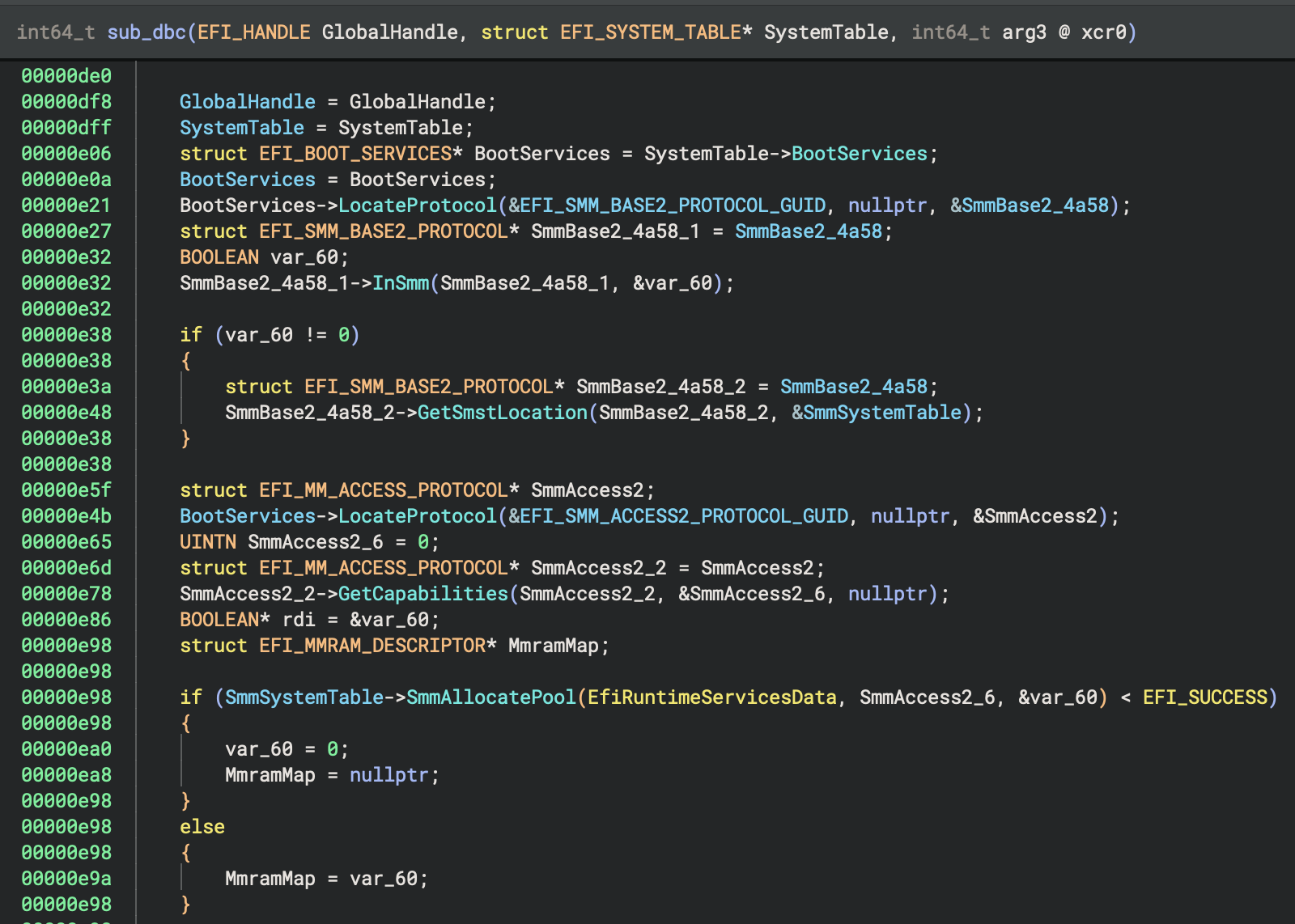
The MM System Table contains MmLocateProtocol, MmHandleProtocol and MmInstallProtocolInterface function pointers
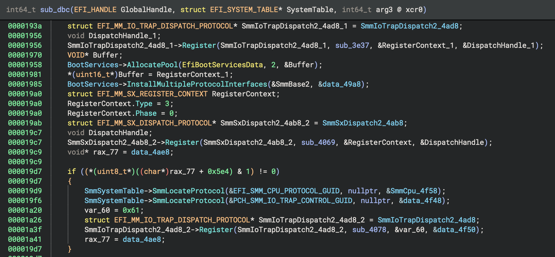
that are typed the same as the function pointers in EFI boot services. As such, EFI Resolver is able to propagate SMM
types and resolve SMM protocols using the same techniques that are used for boot services. The figures below show EFI
Resolver discovery of the MM system table and identification of SMM protocol interfaces.
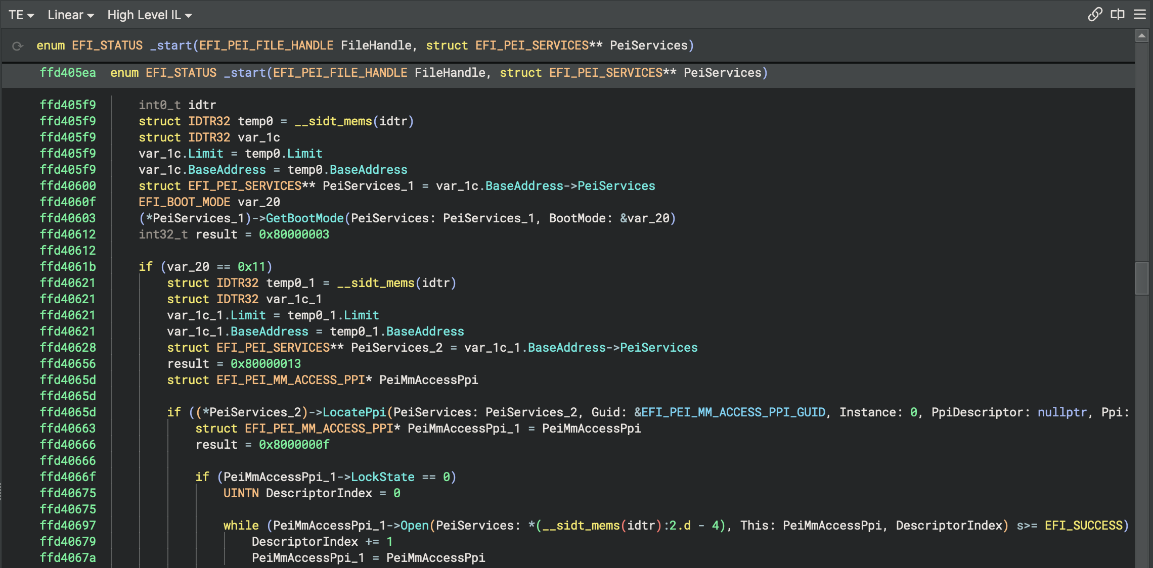
PEI Type Propagation
EFI Resolver propagates types for PEI modules using a similar technique. It starts at the module entrypoint function and
propagates the EFI_PEI_FILE_HANDLE and EFI_PEI_SERVICES types from the function parameters by identifying variable
assignments and callee functions where variables containing these types are passed as parameters using the following entrypoint type:
EFI_STATUS _ModuleEntry(EFI_PEI_FILE_HANDLE FileHandle, struct EFI_PEI_SERVICES** PeiServices)
PEI modules often use processor-specific techniques to retrieve the pointer to the PEI services table. As documented in
the UEFI PI specification,
different platforms store EFI_PEI_SERVICES table pointers to memory regions that are processor-specific. An example of
this can be found in EDK
II.
This code is for x86 (32-bit) and shows that a pointer to the EFI PEI services pointer resides 4 bytes prior to the
Interrupt Descriptor Table (IDT). To access the PEI services, PEIMs query the address of the IDT using the x86 sidt
instruction. The pointer to the EFI PEI services table is accessed relative to the IDT pointer. The snippet below
demonstrates this pattern. Upon execution, eax contains the pointer to the PEI services.
sub     esp, SIZEOF IDTR32
sidt    FWORD PTR ss:[esp]
mov     eax, [esp].IDTR32.BaseAddress
mov     eax, DWORD PTR [eax - 4]
add     esp, SIZEOF IDTR32
On ARM platforms, the PEI services pointer is stored in the TPIDRURW read/write Software Thread ID register. On
AArch64 platforms, it is stored in the TPIDR_EL0 register. The following code snippet reads EFI_PEI_SERVICE pointers
on ARM processors.
ASM_FUNC(ArmReadTpidrurw)
  mrc     p15, 0, r0, c13, c0, 2    @ read TPIDRURW
  bx      lr
EFI Resolver identifies accesses to the PEI services by analyzing HLIL and locating these processor-specific patterns to
apply the EFI_PEI_SERVICES** type to appropriate variables. For ARM and AArch64, EFI Resolver identifies mrc and
mrs instructions. On x86 and x86-64, it is slightly more complicated. As previously mentioned, the PEI services pointer
is stored relative to the IDT. This requires multiple instructions to compute the address for PEI services. EFI Resolver
uses offset pointers to represent the x86 and
x86-64 IDTs. This allows EFI Resolver to simply search for sidt instructions and access the EFI_PEI_SERVICES member
relative to the IDT. The snippet below contains the structure types used by EFI Resolver to identify the access to the
PEI services pointer using Binary Ninja’s offset pointers. By using offset pointers, EFI Resolver can assign a structure
type to the variable storing the IDT register value and access the PeiServices member relative to the IDTR32->Base
member.
struct IDTR32 __packed
{
    int16_t Limit;
    struct PEI_SERVICES_4* BaseAddress;
};

struct __ptr_offset(4) PEI_SERVICES_4
{
    struct EFI_PEI_SERVICES** PeiServices;
    int32_t Base;
};
PEIM-to-PEIM Protocol Interface (PPI) Discovery
Similar to DXE and SMM protocol bindings, PEI modules use PPIs for inter-driver functionality. A producer driver calls
InstallPpi to bind the interface with a GUID and a consumer driver calls LocatePpi to invoke functions provided in
the interface. These functions behave almost identical to the functions used to register and query protocol interfaces
in DXE. The main difference is several PEI services functions (e.g. NotifyPpi, InstallPpi) take pointers to
descriptor structures, which contain pointers to the protocol GUID, instead of directly passing the GUID as a parameter.
EFI_STATUS (* EFI_PEI_NOTIFY_PPI)(
    struct EFI_PEI_SERVICES** PeiServices,
    struct EFI_PEI_NOTIFY_DESCRIPTOR* NotifyList);

EFI_STATUS (* EFI_PEI_LOCATE_PPI)(
    struct EFI_PEI_SERVICES** PeiServices,
    struct EFI_GUID* Guid, UINTN Instance,
    struct EFI_PEI_PPI_DESCRIPTOR** PpiDescriptor,
    VOID** Ppi);

EFI_STATUS (* EFI_PEI_INSTALL_PPI)(
    struct EFI_PEI_SERVICES** PeiServices,
    struct EFI_PEI_PPI_DESCRIPTOR* PpiList);
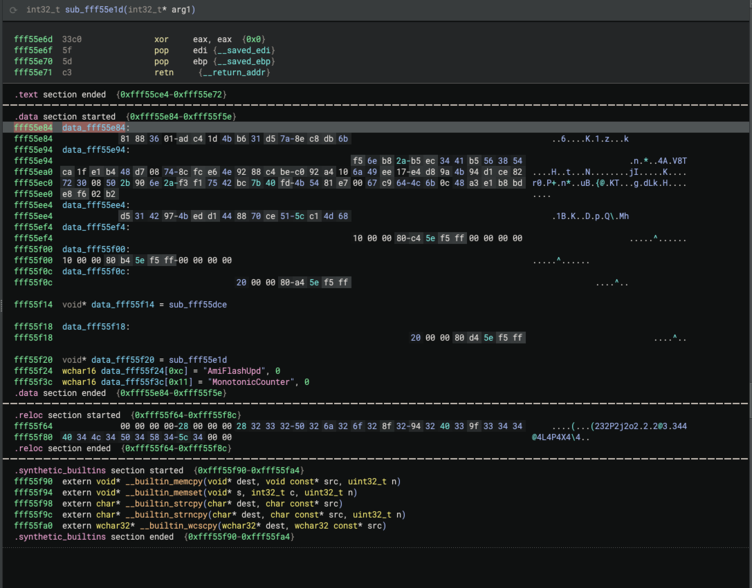
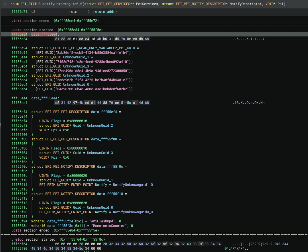
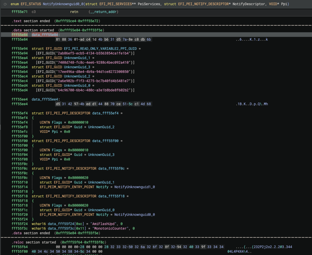
EFI Resolver handles these cases by identifying descriptor structures and assigning types. Most often, the descriptor structures reside in a global data region that EFI Resolver can discover by resolving the value of the descriptor parameter variable. In this case, EFI Resolver assigns the appropriate structure type to the global data. The types for the PEI descriptors are depicted below:
struct EFI_PEI_PPI_DESCRIPTOR
{
    UINTN Flags;
    struct EFI_GUID* Guid;
    VOID* Ppi;
};

struct EFI_PEI_NOTIFY_DESCRIPTOR
{
    UINTN Flags;
    struct EFI_GUID* Guid;
    EFI_PEIM_NOTIFY_ENTRY_POINT Notify;
};
Once the appropriate descriptor type is assigned, EFI Resolver queries the pointer value from the Guid member to
resolve the location of the 16-byte PPI GUID. Additionally, the EFI_PEI_NOTIFY_DESCRIPTOR->Notify member contains a
pointer to a function. EFI Resolver also queries this address and renames the function using the Notify{ProtocolName}
convention. Here’s a before/after screenshot after the EFI Resolver descriptor analysis:
After resolving these descriptors, EFI Resolver propagate types to PPIs. The figure below depicts EFI Resolver
identification of the EFI_PEI_MM_ACCESS_PPI interface.
User-Defined EFI GUIDs and Types
The UEFI specification defines a foundation of common protocols. The types associated with these protocols are included in Binary Ninja’s platform types for EFI. When opening a UEFI DXE or PEI module in Binary Ninja v4.1 or later, these types are automatically available and can be interacted with in types view.
As mentioned previously, UEFI is a specification. Vendors develop their own proprietary flavors of UEFI firmware, which often include their own proprietary types for custom UEFI protocols interfaces. For this reason, EFI Resolver supports user-defined types and GUIDs.
Adding custom UEFI platform types to Binary Ninja is no different than adding types for any other platform. This process
is described here. In order for EFI Resolver to recognize
and propagate a type, a GUID must be mapped to the type. EFI Resolver uses a JSON file (efi-guids.json) to store
user-defined GUID mappings. This JSON file must be placed in the Binary Ninja user directory. This process is described
in more detail in the EFI Resolver
README.
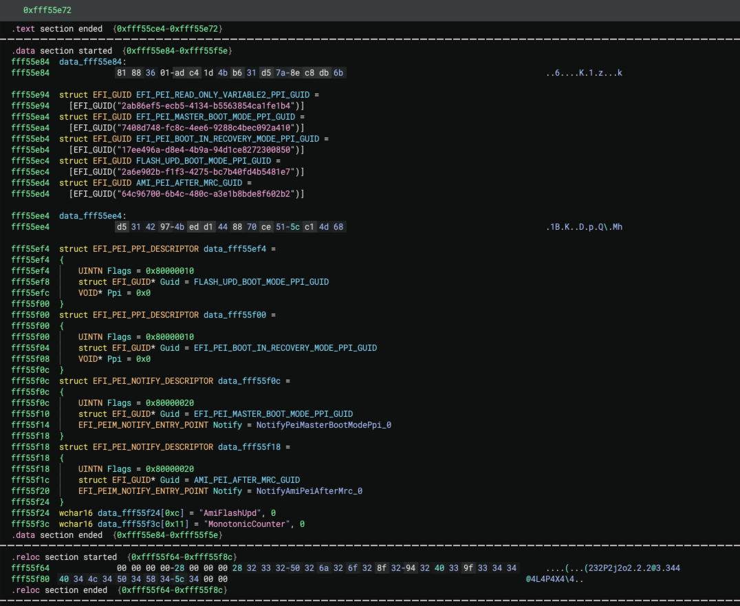
The EFI Resolver JSON file uses the same format as Binarly’s GUID DB. As such,
by copying Binarly’s GUID DB JSON file to the correct location (<user folder>/types/efi-guids.json), EFI Resolver can
use the file to identify and name protocol interface variables. The figure below shows EFI Resolver naming EFI GUIDs and
notification function handlers from protocol GUIDs specified by Binarly’s GUID DB!
Future Work
Work is ongoing to improve UEFI firmware analysis in Binary Ninja. Here are a few additional enhancements on our roadmap:
- Port EFI Resolver to C++ and integrate it into Binary Ninja’s core
- EFI Resolver analysis will fire as part of the initial analysis pipeline; this will improve performance and provide a better out of the box experience
- Add additional types to Binary Ninja EFI platform types
- Automatically identify whether a file is a PEI module or a DXE module (some PEI modules are also PE files)
- Infer structure types for unknown protocols using Binary Ninja’s
create_structure_from_offset_accessAPI - Identify protocols from calls through additional EFI functions (
InstallMultipleProtocolInterfaces,OpenProtocolInformation, etc..) - Automatically name functions that handle System Management Interrupts (SMI)
- Add protocol usage to Binary Ninja’s External Links feature, so that users can link protocol usages to where they are installed
Try it Out!
The features highlighted in this blog post are available in Binary Ninja 4.1 and EFI Resolver 1.2.0. EFI Resolver can be easily installed from the Binary Ninja plugin manager. You can purchase Binary Ninja here. Once you’re all set, take a heat gun to your PC motherboard, pry off the boot flash chip and dump the firmware (or just use chipsec 😉). Be sure to share your feedback with us on the Binary Ninja public slack!
References
如有侵权请联系:admin#unsafe.sh