2024-9-2 22:2:52 Author: hackernoon.com(查看原文) 阅读量:4 收藏
Authors:
(1) Mehdi Naderi;
(2) Markos Papageorgiou;
(3) Dimitrios Troullinos;
(4) Iasson Karafyllis;
(5) Ioannis Papamichail.
Table of Links
The Nonlinear Feedback Control
OD Corridors and Desired Orientations
Boundary and Safety Controllers
Appendix A: Collision Detection
Appendix B: Transformed ISO-Distance curves
Appendix D: Safety Controller Details
Appendix E: Controller Parameters
II. VEHICLE MODELING
A. Vehicle Dynamics
The kinematic bicycle model, that has been extensively used in the literature [11], [12], [36], is employed in this study to represent vehicle dynamics. The model variables are visualized in Fig. 2, and the state-space model reads [11]:

B. Transformation for Circular Movement
While rotating at a roundabout, it is advantageous to transform the above vehicle dynamics to polar coordinates to ease analysis and controller design. Assuming the centre of the roundabout as the origin of the Cartesian and polar coordinates, three new state variables in polar coordinates are defined as below, while the fourth one, i.e. speed, remains unchanged:

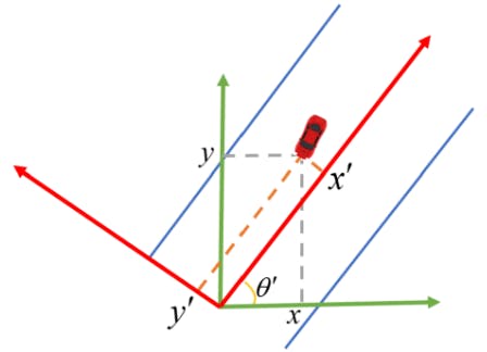
C. Transformation for Skewed Path

![Fig. 2. Illustration of the bicycle model variables [11]](https://hackernoon.imgix.net/images/fWZa4tUiBGemnqQfBGgCPf9594N2-3ac3zk0.png?auto=format&fit=max&w=1080)
![Fig. 3. The transformation for skewed path [34]](https://hackernoon.imgix.net/images/fWZa4tUiBGemnqQfBGgCPf9594N2-itd3z99.png?auto=format&fit=max&w=1080)

D. Sampled-data Bicycle Model
To be implemented in practical frameworks, like simulators, the bicycle model needs to be discretized. Rather than using approximate discretization approaches, like Euler method, the exact sampled-data model is obtained through integrating (1) while considering constant value for control signals during a sampling period. The resulting discrete-time model is [37]:

where k = 0, 1, 2, … is the discrete-time index, and T is the sampling period. For the polar model (5), exact integration appears difficult; hence, we use (8) in the simulation of vehicle dynamics on both straight and circular roads; while the controllers are designed for them based on the respective continuous-time models.
Collision avoidance is the most important goal of control strategies; hence, it is necessary, while simulating vehicle movement, to detect possible collisions among vehicles. Appendix A presents a collision detection procedure for rectangular vehicles.
如有侵权请联系:admin#unsafe.sh